Developing a linear motor car through Model-Based Development (MBD).
2023.12.14
- MBD
With the increasing complexity and scale of embedded software, the development incorporating MBD has become particularly active, primarily in the automotive sector. We have been dedicated to acquiring MBD skills since its early stages, and currently, we are actively pursuing it as a core business initiative.
In the research and development department, we have achieved compatibility with the entire MBD process (MILS, RCP, Code Generation, HILS) for the control of individual motors. Taking another step forward, we are now focused on acquiring practical skills in magnetic control technology, aiming to develop a linear motor car using MBD.
This article will provide an overview of the development progress of the linear motor car.
The characteristics of a linear motor and the operating principles of a linear motor car.
We will explain the characteristics of a linear motor and the operating principles of a linear motor car.
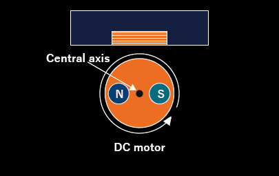
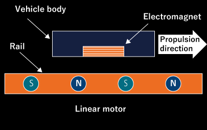
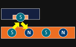
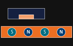
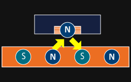
A typical DC motor generates rotational motion by controlling the magnitude and direction of current to an electromagnet (stator), causing the rotation of a permanent magnet (rotor) located inside. On the other hand, a linear motor is distinctive for producing linear motion. In the case of a linear motor, the permanent magnet inside the DC motor is elongated in a linear fashion, with North poles and South poles arranged alternately in a straight line. Additionally, an electromagnet, which serves as the stator, is mounted on the vehicle, generating propulsive force by creating a magnetic field through the magnitude and direction of the current flowing to the electromagnet.
Vehicles that utilize this linear motor for acceleration and deceleration in the direction of travel are referred to as linear motor cars.
Construction of the linear motor car's body and course, development, and validation of the speed measurement system
This development began with the fabrication of the body of the linear motor car and the course (rail) on which the vehicle body moves. Subsequently, the creation of controller and plant models was undertaken. Currently, we are progressing by comparing MILS results with the actual vehicle, refining both the actual device and the model.
Firstly, let me introduce the linear motor car's body and course that we constructed. The body's casing and the course were designed and manufactured using a 3D printer that we own. Additionally, we have developed a system to measure the speed of the vehicle traveling on the course and are conducting real-world validations.
Firstly, let me introduce the linear motor car's body and course that we constructed. The body's casing and the course were designed and manufactured using a 3D printer that we own. Additionally, we have developed a system to measure the speed of the vehicle traveling on the course and are conducting real-world validations.
Fabrication of the Linear Motor Car's Body and Course
Vehicle Body
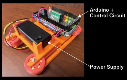
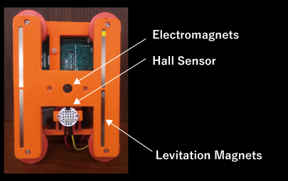
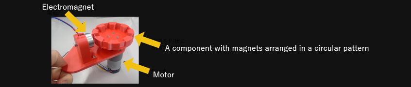
Introducing the fabricated vehicle body and installed components.
| Details of the Vehicle Body | Surface: Electronic circuits for Arduino control, Power Supply. Back Surface: Electromagnets, Hall Sensors, Permanent Magnets for Levitation. * Rollers are also installed to ensure smooth navigation along the course. |
|---|---|
| Operating Principle |
|
Vehicle Body - Surface
Vehicle Body - Back Surface
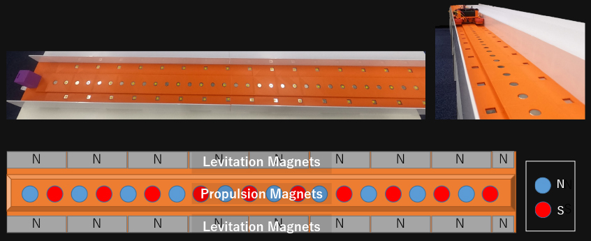
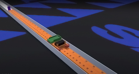
Course
On the constructed course, we have positioned propulsion magnets and levitation magnets.
The propulsion magnets are arranged with permanent magnets in a regular pattern of alternating north pole and south pole, and on both sides, levitation magnets are placed to lift the vehicle.
The propulsion magnets are arranged with permanent magnets in a regular pattern of alternating north pole and south pole, and on both sides, levitation magnets are placed to lift the vehicle.
The constructed course (rails)
Please observe the actual operation of the constructed linear motor car in motion.
Development of the speed measurement system and verification of speed control accuracy
To verify the precision of the vehicle's speed control, we developed a speed measurement system using a wide-angle web camera.
We installed a wide-angle web camera to capture the entire track, enabling us to measure the speed of the vehicle as it travels along the course.
We installed a wide-angle web camera to capture the entire track, enabling us to measure the speed of the vehicle as it travels along the course.
Measurement Process
- Initiate recording and correct distortion using a wide-angle lens.
- Utilizing an object detective algorithm, detect moving objects within the video, and measure speed based on changes in frames.
- Record in time [s] and speed [m/s], and output in CSV format.
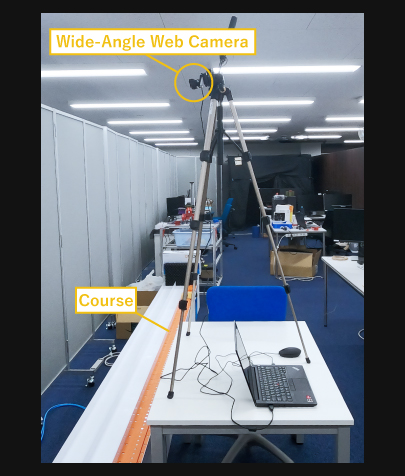
Speed Measurement System
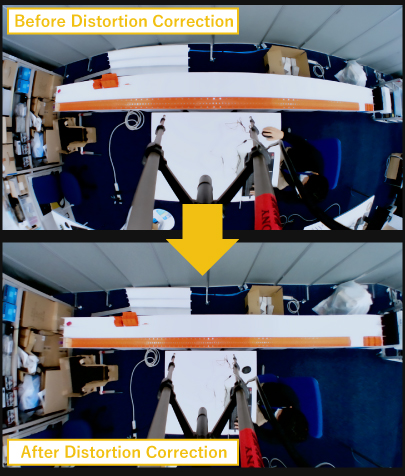
Distortion Correction Process
These are the actual measurement results during the test run at a speed of 1.5 km/h.
We are exploring improvements to the vehicle and track to achieve stable attainment of the target speed.
We are exploring improvements to the vehicle and track to achieve stable attainment of the target speed.
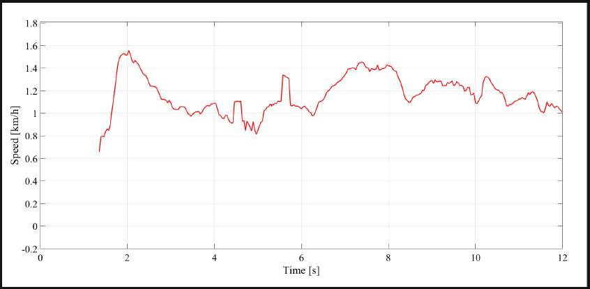
Measured Results from the Test Run
- Initiate recording and correct distortion using a wide-angle lens.
- Utilizing an object detective algorithm, detect moving objects within the video, and measure speed based on changes in frames.
- Record in time [s] and speed [m/s], and output in CSV format.
From the constructed linear motor car, we developed controller and plant models
We will now introduce the created controller model and plant model, respectively.
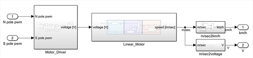
Creating the Plant Model
We are creating the plant model by combining the electromagnets and hall sensors installed on the vehicle body, along with the linear motor track.
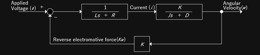
The linear motor operates in a linear motion, but its control logic can be considered similar to that of a DC motor.
Therefore, the linear motor can be represented with the same mathematical model as a DC motor.
Motor parameters are measured, sometimes by creating custom measurement devices, to model the linear motor.
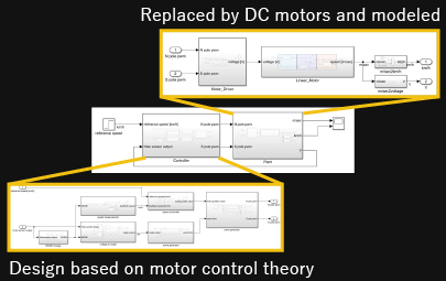
Creating the Plant Model
Converting the rail from a linear system to a rotational system and creating a model as a DC motor.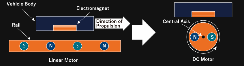
Each parameter is measured by building your own measuring device, etc.
DC motor block diagram
Reverse electromotive force measurement device
Plant model
Creating a controller model (magnetic force control for maximizing thrust)
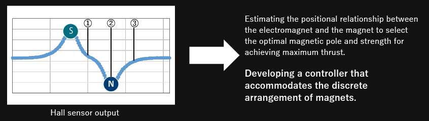
In the controller, we developed a new algorithm to constantly generate thrust from the electromagnet.
We estimate the positional relationship between the electromagnet and the magnet, selecting the optimal magnetic pole and strength to achieve maximum thrust.
This has enabled the creation of a controller that corresponds to the discrete arrangement of magnets.
We estimate the positional relationship between the electromagnet and the magnet, selecting the optimal magnetic pole and strength to achieve maximum thrust.
This has enabled the creation of a controller that corresponds to the discrete arrangement of magnets.
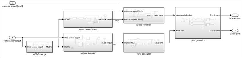
Creating the Controller Model
Developing an algorithm for continuous propulsion generated from the electromagnet.
Creating the Controller model
①
②
③
Controller model
Comparing MILS results with actual device and refining the model to be closer to the real-world performance
We integrated the created controller model with the plant model and conducted MILS.
We are comparing MILS results with actual device and working on improvements to make the model more closely resemble the real-world performance.
We are comparing MILS results with actual device and working on improvements to make the model more closely resemble the real-world performance.
Due to the development progressing from actual device production to model creation, there was an initial discrepancy between the created model and the actual device. However, through iterative improvements to the model, it has gradually become more of the real-world system.
Moving forward, We will continue comparing MILS results with actual device and work on further improvements to the model.
Moving forward, We will continue comparing MILS results with actual device and work on further improvements to the model.
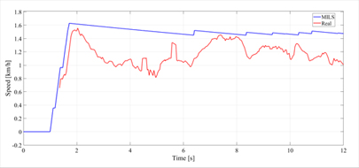
Comparison between MILS and the actual device (Blue: MILS, Red: Actual Device)
In pursuit of acquiring more practical MBD skills, our research and development department is taking on the challenge of developing a linear motor car using MBD.
Through the process of actual device production, model creation, MILS, and actual device validation, our proficiency in magnetic control technology and the ability to create models closely resembling the real-world system have significantly improved.
Moving forward, we will continue to enhance the vehicle and track, considering improvements, refining the model's accuracy, and advancing initiatives for the future, such as the following.
- Conducting research and experiments on 3D physical simulation to establish a mechanism that can simulate actual operations even in the absence of an actual device.
- Anticipating the future of transportation and logistics systems, we aim to create a two-dimensional linear motor car capable of movement in both horizontal and vertical directions.
Unity 3D physics simulation